


|
|
The stepper motor and valve when removed from the engine............ |
|
|
...........and separated. |
|
|
After 13 years of use, this was how dirty mine was ! |
|
|
After cleaning, this is what it should have looked like. |
|
|
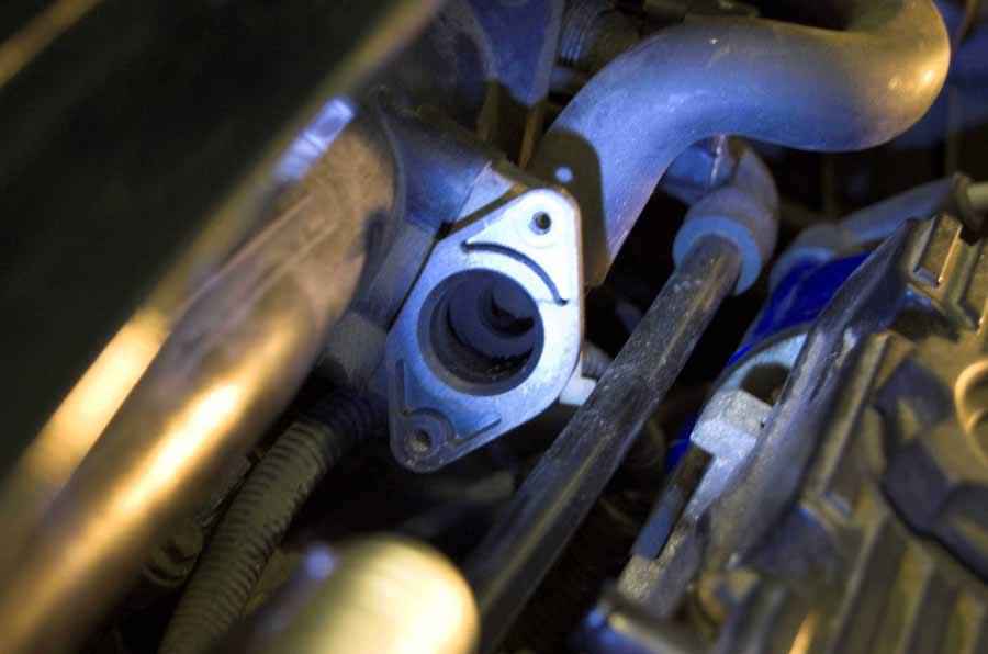
Similarly, you can see that the valve port also needed cleaning. |

|
The stepper motor is here. |
|
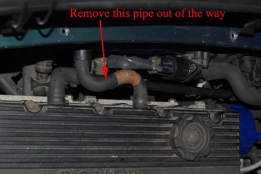
To give better access to the lower fixing screw, use a pair of pliers to release the pipe retaining clip and pull off the pipe from the engine head, and then from the manifold. |

|
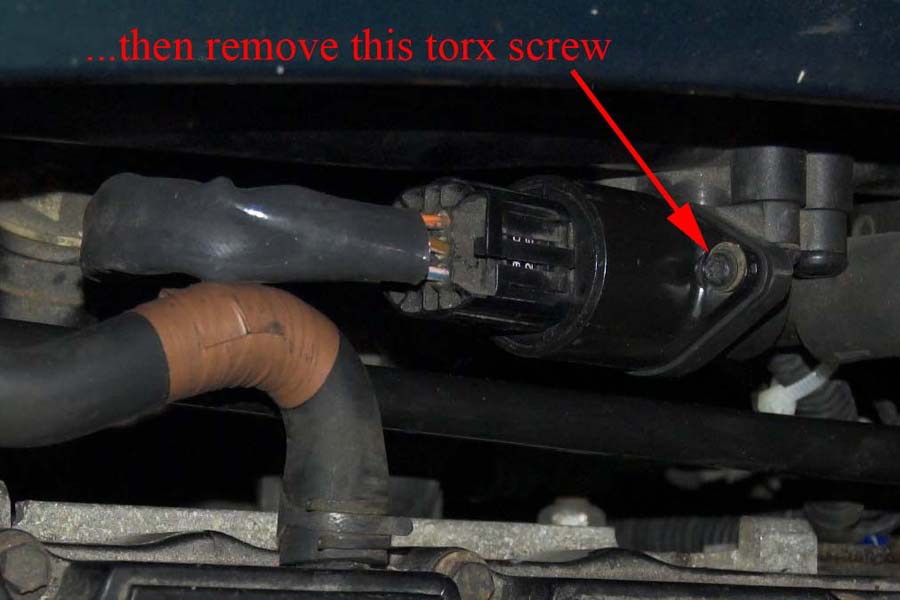
Then depress the connector-retaining clip (part of mine has broken away!) and pull off the connector and move it aside. |
|
Then undo and remove the top torx screw. |
|
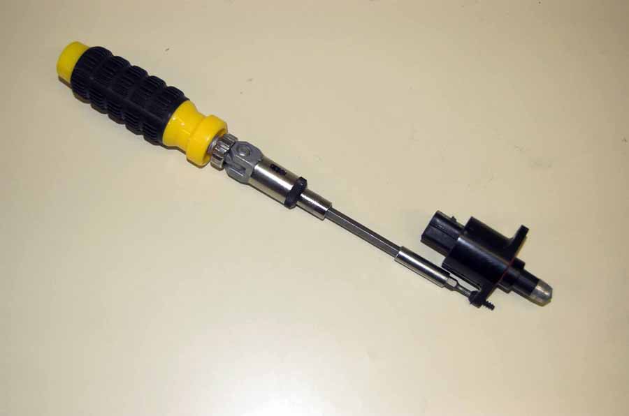
The lower torx screw is harder to see and more likely to be dropped! I suggest that you use a long-reach driver. Locate it in the screw head and as you undo it, use your other hand to pull and lift the stepper motor up and away from the engine, while retaining the screw still in the motor flange. You are far less likely to loose the screw somewhere down in the bowels of the engine bay. Use the same principle in reverse when refitting the motor. Remember that the torx screws are fitting into plastic - the recommended torque value is only 1.5Nm ! |
|
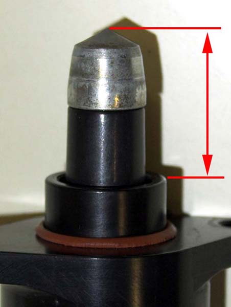
I would suggest that before you test the stepper motor, you should measure the amount that the 'bolt' sticks out of the body. Testing will alter this length and since this is the position last determined by the ECU, it is probably the best starting position when refitting the motor if it passes the following test.
After adjusting and measuring mine, I have the impression that when the valve is fully closed, this measurement is between 28mm and 29mm, and it's normal running position when the engine is hot is therefore between 25mm and 28mm, though I cannot guarantee this. |
|
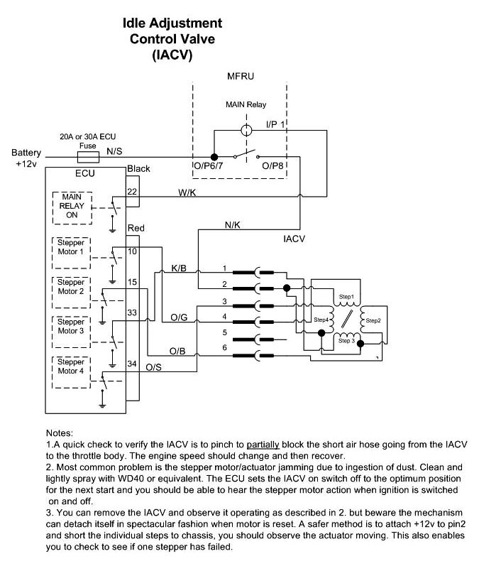
As the circuit diagram and notes state, it is possible to test the stepper motor by applying 12v to Pin 2 and sequentially connecting GND to Pins 1, 3, 4, and 6.
Circuit courtesy of Tom White, Switzerland |
|
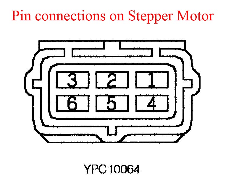
To extend the bolt outwards follow the sequence of Pins 4, 6, 1, 3. You can repeat this sequence over and over again to move it further, but don't do it too far. You should feel a step movement each time you make contact with a pin, though if the motor is already in the position relative to the pin connector you initially make contact with, there will be no movement. On subsequent loops around the sequence, it should cause movement.
To retract the bolt inwards follow the sequence of Pins 3, 1, 4, 6. You can also measure the resistance across each circuit. Mine measured 8.8, 8.8, 8.7, and 8.8 ohms. If the movement and resistance is consistent, then the stepper would appear to be working okay, and I would suggest that you 'drive' back so that it is left in the same position as when you measured it earlier. |
|
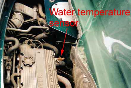
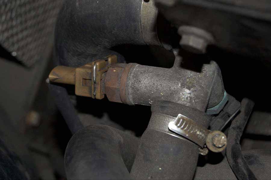
Easily distinguished since it is coloured brown. |
|
Remove the spring clip from the connector using long-nosed pliers........... |

|
......and set clip aside. Then remove multi-plug connector. |

|
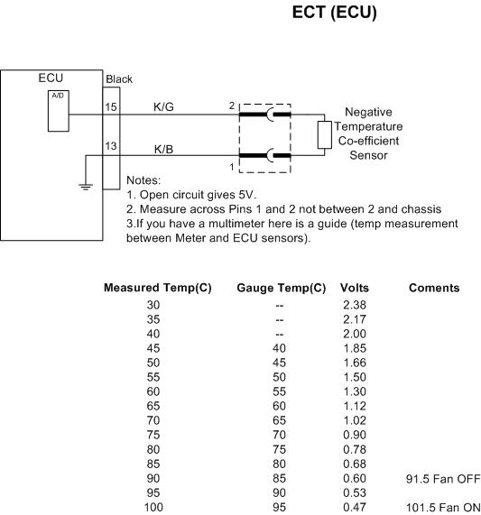
Before removing the sensor, you can make a quick check with a multi-meter across the pins to see if the sensor has gone open circuit - i.e. no connection. If you are going to replace it immediately, there will be a small amount of coolant loss. You will need a 19mm spanner to undo it. Wait until the engine is cold, so that the thermostat is closed (it will reduce the coolant flow), and have your thumb ready to block the hole. Ideally you should replace the washer on the sensor with a new one (it is not supplied with the sensor!), but the existing washer should do the trick if need be. Remember to later check for leaks once the engine is back up to running temperature. |
|
Temp Resistance 0 4.8K-6.6K 10 4.0k 4.0k 20 2.2k-2.8k 30 1.3k 1.3k 40 1.0k-1.2k 50 1.0k 1.0k 60 800 800 80 270-380 Circuit courtesy of Tom White, Switzerland |

