During this summer of 2011, after my coolant level alarm has been working for the last 6 years, the alarm started to go off fairly regularly, although every time I checked the expansion tank, there was no problem with the level of coolant. Even with a cold engine, and using a screwdriver to push the float down, everything seemed okay.
The problem slowly became worse, until it was triggering virtually constant, and with the noise of the buzzer in the car driving me and my wife mad, there was no option but to disconnect the thing. Luckily, by having built a fuse into the 12v supply, it was simple enough to do.
Stripping the circuit board out of the car, and bench testing it with an oscilloscope, I still couldn't find a problem, so back in the car it went for further testing. I added an extra 12v light into the circuit, between the return wire from the hall-effect sensor and ground, so I would be able to see immediately the sensor tripped, rather than wait for the delay circuit to turn on the buzzer and the original led.
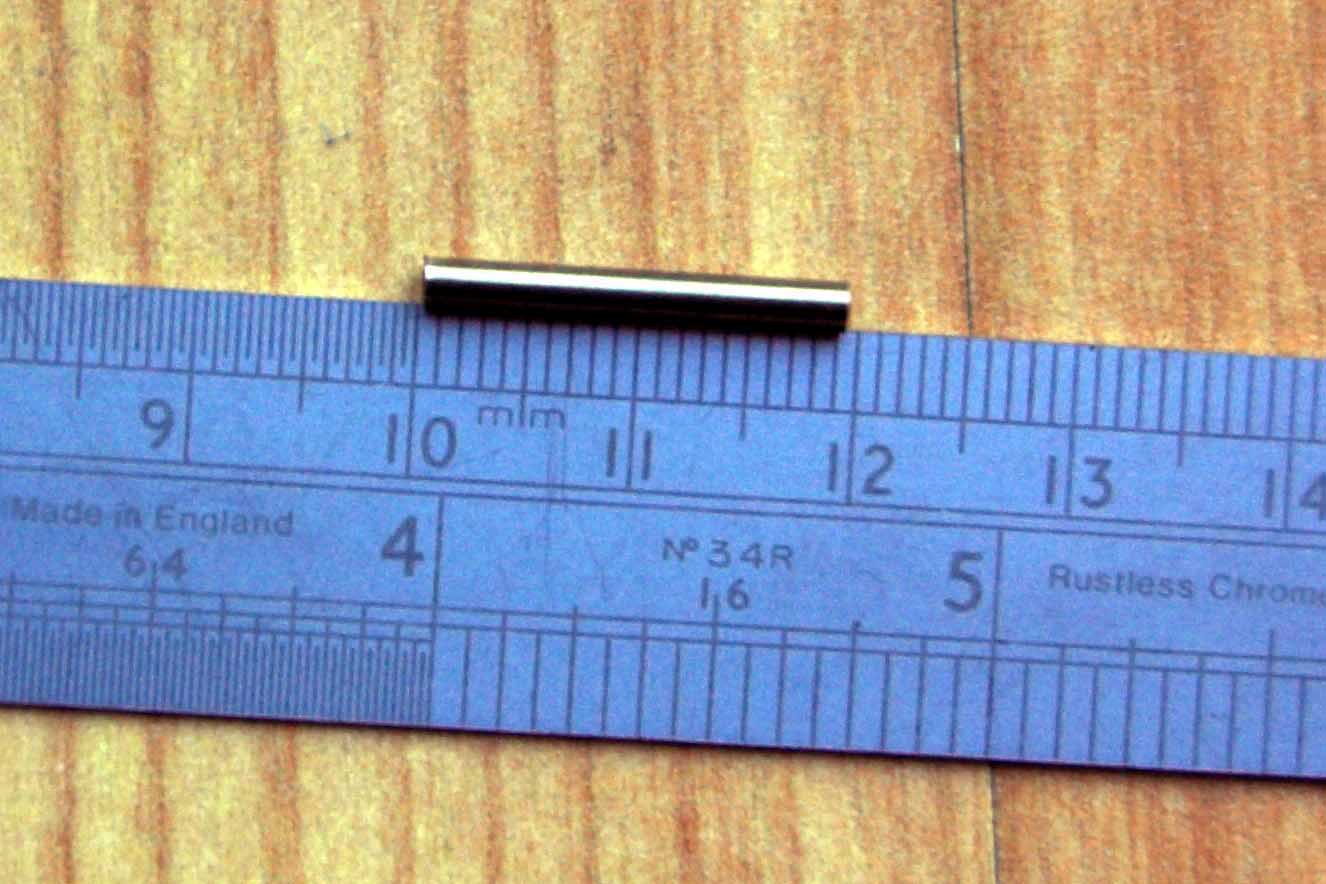
 However.........................while trying to static test it again, pushing the float down with a screwdriver, it failed to work at all. What did happen is when I pulled out the screwdriver, there was this small 19mm long magnet stuck to the end.!!!!

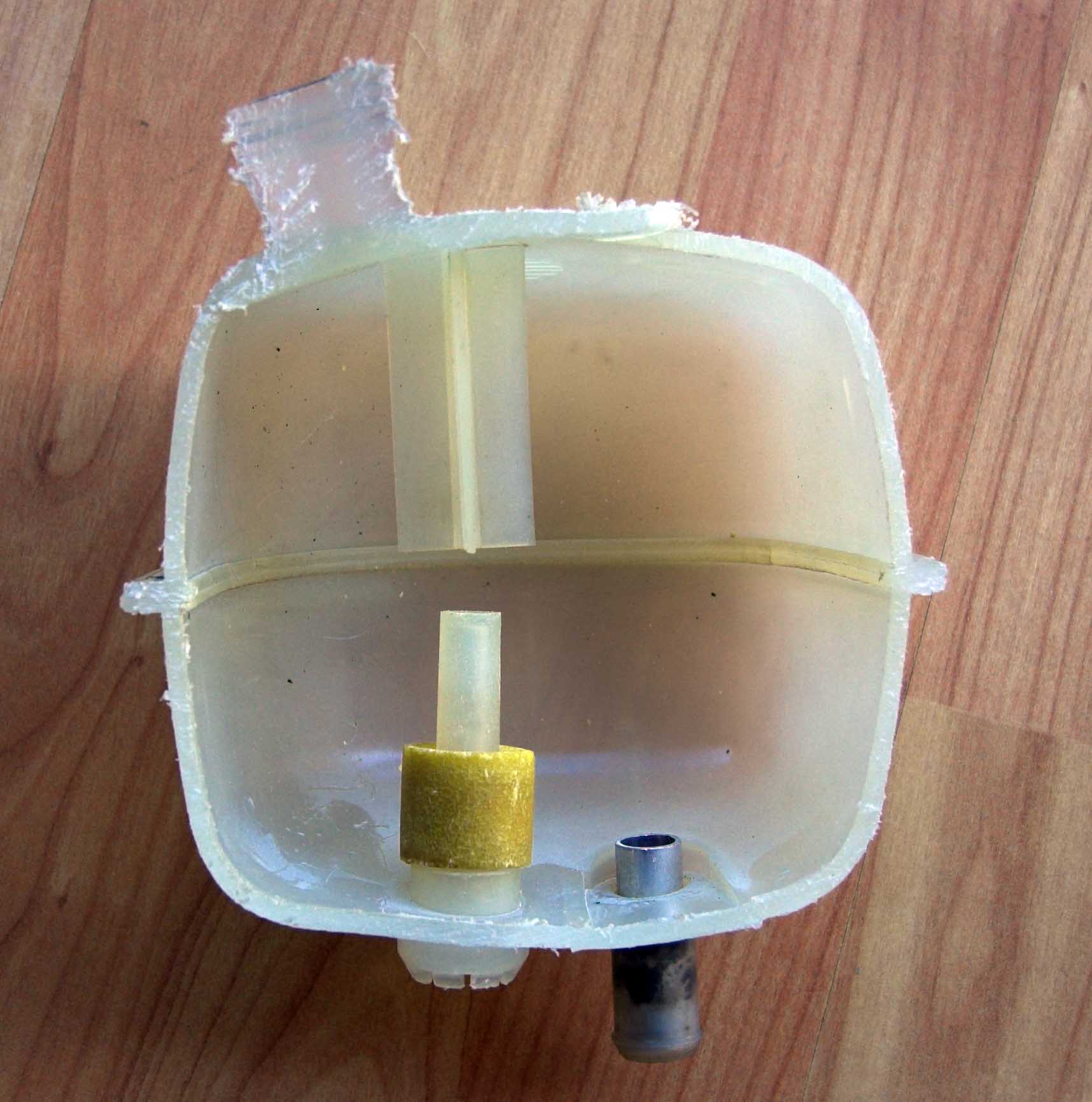
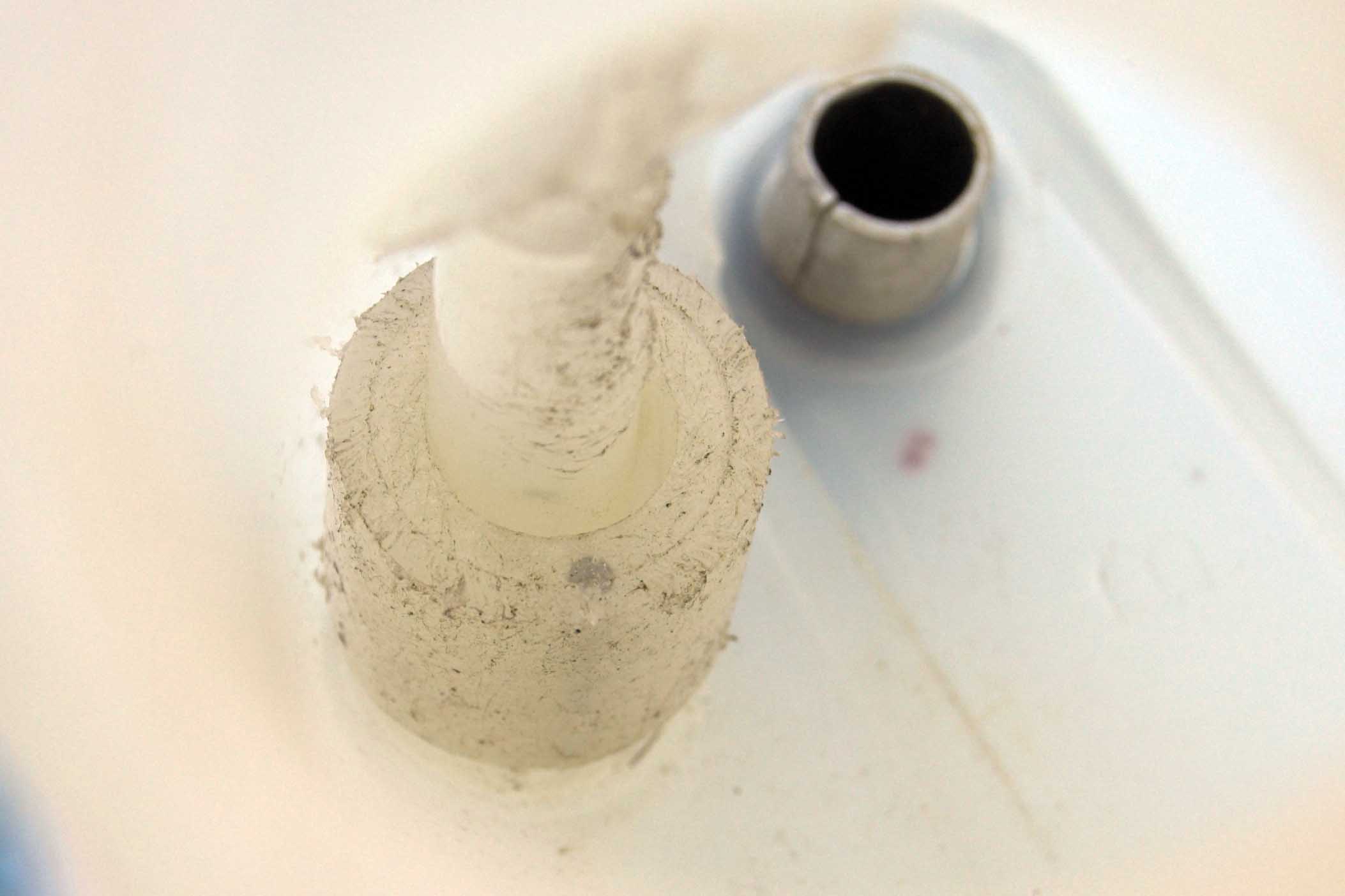
 With half the tank cut away, and upside down, you can see the hole that used to hold the magnet.
 What appears to have happened is that the magnet, fitted vertically into the float, has been slowly dropping out, triggering the alarm prematurely, but each time I tested the alarm, by manually pushing the float down to the bottom of the tank, the magnet has been pushed back in, only to slowly work it's way out again.
Since the float and magnet cannot be replaced, the only option was to purchase a new expansion tank. The float in the new tank appears to have been redesign, with the magnet or magnets being embedded in the float horizontally (not shown), though it's very difficult to see and be sure. Also, note how the colour and nature of the float in my tank has degraded, when compared with that of the float in another old and not much used tank (see photo on the left)
Since this problem is due to a failure of the float and magnet in the expansion tank, and is not directly related to the electronic alarm itself, I think that it is highly likely that it may occur with any low level alarm system on the market.
ALARM CIRCUIT DESIGN
The early MGF's and TF's coolant expansion tank did not include a built in level sensor & alarm, though one has been recently introduced.
The simplest alarm would be to connect a dash mounted bulb or LED, and a buzzer, straight onto the output of the sensor that fits in the bottom of the coolant header tank. These would immediately turn on as soon as the level of coolant in the tank dropped. Driving a MGF, if one was to take a sharp turn to the left at about 20 MPH, or a gentle turn to the left at about 70 or 80 MPH, the coolant in the tank is forced to the right and the level at the sensor can drop. This would then turn the light & buzzer on briefly, until the level of the coolant returned to normal. With a lot of turning, these false triggers would become very annoying.
The idea of my circuit is to delay turning on the light and the buzzer for a number of seconds so that you are then certain of a true alarm. When the sensor detects low coolant, it starts to charge up a capacitor, and when that charge reaches 6v, the light and buzzer are turned on. The length of time it takes to reach that point is controlled by the 2 variable resistors that sit side by side in the circuit, and adjustment can vary the time from very small delay, to up to about 9 or 10 seconds. Mine is set around 6 seconds.
When the sensor detects that the coolant level has returned to normal, the third variable resistor controls how quickly the capacitor charge decays before turning off the light and buzzer. The idea is that should the sensor detect rapid and consecutive falls and rises of the coolant, the charge in the capacitor would still build up ( bit like a saw tooth pattern ) and eventually trip the alarm.
I purchased and fitted the new expansion tank, Part Number PCF000141 - perhaps it is now the standard. Just make sure when you get buy the tank that it has the internal float and 'hole' in the bottom for the sensor. The sensor is PCJ000040 and costs £9.60 from Rover. The tank was £ 26.08, again from Rover (both prices include VAT).
The new expansion tank is basically the same as the original, except that there is a vertical pillar inside the tank and a float that is free to ride up & down the pillar. On the bottom face of the tank is a hole that allows the sensor to fit inside the pillar.
The connector for the sensor is the same as that for the, I think, the Air Temperature Sensor, and is an AMP 347882 2-pin connector. This appears to be a special, since details cannot be found on the Tyco/AMP website.
The Buzzer I used is a SoundTech SEP-2232A - See below for the Data Sheet..
My initial circuit was extremely simple - too simple as it turned out! An in-line fused 12v supply was fed to a 12v red LED and paralled 12v buzzer. The buzzer needs to be able to output about 92 dB to ensure you can hear it at speed with the roof down! These were connected to one side of the level sensor, the other terminal going to ground. This worked fine, provided you could tolerate the "in-built auto circuit tester" every time you went round a sharp bend or down a bumpy road. Even with the expansion tank filled to it's maximum limit, there was too much 'slop' of the coolant.
 This shows a place from which to take the 12v supply.
There obviously was the need to build in a delay circuit so that the alarm was only triggered after the float remained 'low' for several seconds. The time period really had to determined by trial and error, so it was essential to build in adjustment to the circuit, of something in the order of 2 to 10 seconds.
FINAL CIRCUIT:
The Overall Scheme reverses the layout, in so much that the fused 12v supply is fed initially to the float sensor, and the output from the latter is then fed to the Delay Circuit Diagram. Everything is still 12v based, cutting down on complexity, and the adjustable resistors allow for a time delay range of somewhere between 4 to 10 seconds.
Holes drilled in the sides of the enclosing box allow for cable entry and also for tweaking the variable resistor pots. The box itself is velcro'd to the inside of the fuse panel, so as to allow for easy access/removal, and also to avoid drilling holes into the panel.


 I am sure that if I were to rebuild it, the whole PCB size could be reduced with an improved component layout.
This system is now in my car and being road tested. Initial results seem fine - no false tripping, and a static test of forcing the float down for 4 seconds trips the alarm. This will now form part of my daily/weekly coolant level check, to ensure the system is still active and okay. More information when we return from the Pyrenees.
Wire routing:

 It is possible to run a wire from the engine bay to the interior of the car without removing the T-bar and drilling holes. If you look at the bonnet release lever in the boot, and follow the cable forward along the inner wing, the cable runs through a gap in the body panels and runs underneath the carpet adjacent to the door seal. Using a wire-leader or narrow rod, it is possible to feed a new wire though this gap, and then forward to the fuse box, or across under the carpet to the central console.
UPDATE: 25 June 2005
We have just returned from our 2000+ mile road tour down to the Pyrenees in southern France and Spain (and what a great tour it was), so I thought I'd write an update on how my Coolant Level Alarm system worked.
During all normal road driving there was no problem, and it wasn't until we started driving in the actual Pryenees mountains, with lots of very tight hairpin climbs and descents that the alarm tripped, but only very, very briefly, and only the once. Driving speeds were relatively low, probably down to 10 / 20 mph on a lot of the corners.
With the timer set at approx. 4.5 seconds, the most the float could have been down near the bottom of the tank was about 5 seconds.
However, as we started our return journey, heading north on the A75 from Beziers and up towards the new bridge at Millau, the experience was a lot different. This route is a relatively new motorway, climbing and dipping through a very rugged area, with long sweeping curves. At high speed (no - all I'm saying is 'high' so don't ask!) the alarm tripped regularly on the left hand bends, especially those that dipped down, swung left, and then climbed, and it stayed on much longer, to the point that I began to worry. Out of the bend, a quick flick of the wheel, and it shut up. I've tried to estimate how long the buzzer might have been on, and I guess somewhere around 6 - 8 seconds is near the mark. That means a total of about 10.5 - 12.5 seconds.
Rob Bell comments:
"The principle of the expansion tank is that it isn't actually part of the normal circulation of the coolant system - i.e. water isn't actually pumped through the tank. The purpose is for it to act as a reservoir - where when the coolant volume expands under increasing temperature, the excess drains into the tank. Then, after the ignition is switched off, the contracting coolant draws fluid in from the expansion tank.
The two jiggle valves constrain the fluid entry to the expansion tank. To my knowledge, there is no non-return valve in the expansion tank outlet. However, the system is under pressure, and therefore, there ought not to be any flow through the expansion tank outlet unless, for what ever reason, there is a loss of pressure in the main coolant circuit.
Therefore I would say that there isn't anything to worry about Tony, even if the expansion tank outlet is exposed to air for a period of seconds under hard cornering.
Perhaps a much longer delay period needs to be built in (especially for those MGF/TF owners who want to take their MG on track)? 10 or 12 seconds perhaps?"
Feel free, but remember to do the usual visual checks and, if you copy it, test the circuit every now and then. I will accept no responsibility.
PDF files
 If you don't have Acrobat Reader, click the button on the left to download it for free.
 Circuit Overview
 Circuit Diagram
 SEP-2232A buzzer


